Demosaicing: Constructing RGB pixels from a Bayer mosaic
Here's my understanding regarding RAW files and how they are rendered into familiar RGB photo files:
- Most cameras use a colour filter array in a Bayer mosaic pattern.
- Each RAW pixel in a RAW file reports the amount of light of a single colour (red, green, or blue) that fell upon that location.
- The each of the three colour values in each RGB pixel are generated from the RAW file by combining information from at least four neighbouring RAW pixels.
- The fields of RAW pixels used to generate RGB pixels overlap, allowing the RGB image to have as many pixels as the RAW image.
- There are many different possible interpolation algorithms available to combine RAW pixels into RGB pixels, each with pro's and con's.
- The most common algorithm is Adaptive Homogeneity-Directed (AHD), but better algorithms are available.
- Some algorithms perform better along straight edges; some have the effect of 'sharpening'.
- Of the major RAW processing software packages I've looked at, RawTherapee offers best control of the demosaicing process.
Most digital cameras use a colour filter array (CFA) to make each of their sensors (photosite or sensel) 'see' only one of three primary colours: red, green, or blue. The CFA is organized in what's called a Bayer filter mosaic (figure 1b). Each square in figure 1b represents a sensor value in a raw file, straight from the camera, of a photo of the edge of a razor blade edge (figure 1a), transitioning from nearly-black at the top to nearly-white at the bottom. (For the moment, ignore the yellow and white boxes.)
There are twice as many green squares as red or blue because evenly arranging three colours across a two-dimensional array calls for duplicating one of the colours; green is picked to be duplicated because it is more important to our eyes than the other two colours.
The colour is the colour of the Bayer filter at that RAW pixel, and its brightness indicates the amount of light of that colour that fell on that pixel. In this image (figure 1b), the top part was nearly-black and so none of the red, green, or blue sensors received much light; the bottom part was illuminated by white light, which of course is composed of red, green, and blue components, and so each of the red-, green-, and blue-filtered sensors reported high values, represented in figure 1b as bright colour values.
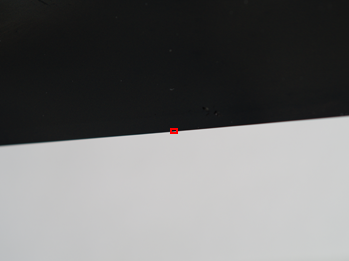
Fig 1a. A photo of the edge of a razor blade lying flat, such that blade makes a sharp edge between nearly-black and nearly-white. The raw file pixels corresponding to the area marked by a red rectangle are shown in figure 1b.
|

Fig 1b. Each square represents a sensor value from a raw file for the photo in figure 1a in the area of the red rectangle. The yellow and white boxes identify overlapping groups of 2x2 pixels that contribute to two single RGB pixels in figure 2.
|
Figure 2 shows what the RGB pixels look like when the Bayer mosaic data of figure 1b have been converted to RGB pixels. The pixel in the yellow box below (figure 2) is based upon the four pixels in the 2x2 yellow box in the figure above (figure 1b); similarly for the white boxes. Each pixel in the RGB result (below) comes from (via interpolation) four pixels in the raw image, but since there is an overlap, each raw pixel contributes to four demosaiced pixels and the end result is an image with the same number of pixels as in the raw file.
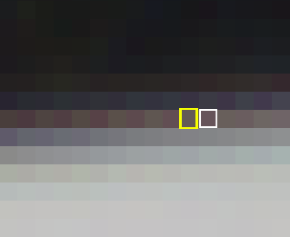
Fig 2. Each square represents a RGB pixel derived from raw pixels in figure 1b. The RGB pixel in the yellow box was derived from the four values in the yellow box in figure 1b; similarly for the RGB pixel in the white box. In this manner, each raw pixel contributes to four different RGB pixels.
This is just one of any number of possible ways of converting raw pixels to RGB pixels; the method used to produce this image is basic and has shortcomings (notice the artifacts, eg., pale false colours, and faint 'on/off' pattern along rows).
There are many possible ways of doing the interpolation part of the demosaicing process. The image above (figure 2) was created by a raw file analysis application called RawDigger with a simple demosaicing algorithm that has artifacts: Notice the false colours (the subject was purely black and white) and repeated faint on/off patterns introduced along a row. A better algorithm, called Aliasing Minimization and Zipper Elimination (AMaZE), was used by RawTherapee to create the image below (figure 3) from the same raw file (figure 1b).
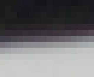
Fig 3. RGB pixels as created using the Aliasing Minimization and Zipper Elimination (AMaZE) demosaicing algorithm. With this algorithm, each RGB pixel may rely upon more than four raw pixel values.
So even the conversion of the raw Bayer mosaic to the familiar RGB pixels involves decisions that can affect the RGB image quality.
Most raw converters and cameras don't offer a choice of demosaicing algorithm; they apply a fixed algorithm when the raw file is opened. A commonly used algorithm is Adaptive Homogeneity-Directed (AHD) demosaicing. RawTherapee (v4.2) offers many choices (figure 4), with AMaZE as its default ('none' renders the raw Bayer pixels, as in figure 1b).

Fig 4. RawTherapee (v4.2) user interface for selectiing a demosaicing algorithm.
Here's a thread to get deeper into the topic of demosaicing algorithms, and into digital sensors: Olympus microscopy resource: Digital sensors.
I created a web-based tool (PGM File Viewer) that can be used to explore RAW files before and after demosaicing. PGM files are created from RAW files using dcraw, as described on the PGM File Viewer info/about page.
Comments or suggestions